SUM3D
3D CAM for CNC machines and robot
 CAM Experience – Functionalities
The wide availability of file readers gives total compatibility with all CAD/CAM systems. Many of these formats are incorporated in the SUM3D basic configuration including: Iges, Dxf, 3dm, Parasolid, Vda, and Stl. Other available options are: Catia v4 and v5, Unigraphics, Step, Inventor, SAT, TopSolid and Pro|E. There is also a component, that can be installed on SolidWorks, which exports 3D models with features that will be managed by SUM3D.
All available interfaces can recognize the hole diameters, resulting in faster machining operations on them (drilling, threading, reaming, etc.) The close integration with Rhinoceros permits automatic change updates on profiles and surfaces without any model reimportation.
SUM3D manages different types of archives where it is possible to insert the tools and components, machines and typically used machining.
After the definition of these archives, the use of repetitive data will be reduced to a basic selection, thereby avoiding data entry errors and creating a database containing the company’s experience.
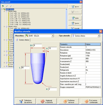
Interface used for tool introduction, in addition to all dimensional and technological parameters, permits tool life definition, programming the postprocessor for tool change insertion (twin tool) or a pause for tool check.
A sequence of tools can also be assigned to a single machine thereby creating its own tool store. With all SUM3D machining any tool shape (flat, bull and spherical) can be used.
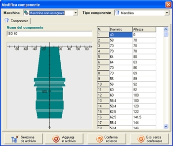
The possibility of drawing tool components (tool holder, mandrels, etc.) enables toolpath calculation in order to improve graphic simulation with the possibility of collision checks with whole tool body, pliers, mandrel, etc. while working in maximum safety.
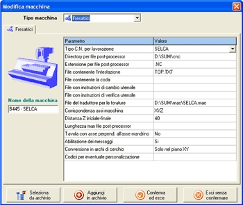
A real machine tool can be configured inside SUM3D, including both Milling and WireEDM machines. Machines can be defined with all types of postprocessor without additional cost.
Head, tail, tool change, tool check, fixed drilling cycles, the use of G2/G3 and machine axis settings can all be customized in this archive.
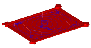
After importing the model, the position and orientation can be modified by using several specific controls capable, for example, of creating zero pieces for machining.
If it is necessary to make changes to the model, such as parting surface, closure of slits and holes or nonworking areas or consideration of new equipment special functions exist for the creation of curves or surfaces as well as many other controls for the creation and manipulation of curves for definition or delimitation of the work areas.
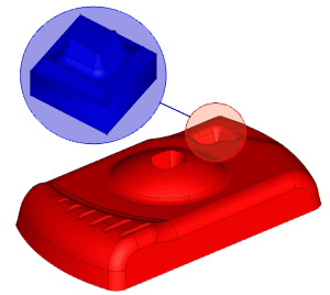
If some parts of the model are needed to perform raw plug or electrode machining, the portions of surfaces exporting control can be used.
This will cut out the selected area and save it in a new CAM file. Work on non finished parts (melt parts, preworked parts, etc.) is facilitated by the raw part management functions.
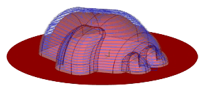
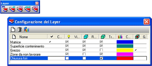
This group of controls permits both the use of a raw part mathematical model for importation together with that to work as well as direct creation of the raw part in the SUM3D environment. The use of layers permits management of these surfaces that can be transparently visualized or not, defining the raw part property. Layer management is also very useful for identification and characterization of the different parts of a model, permitting visibility only when
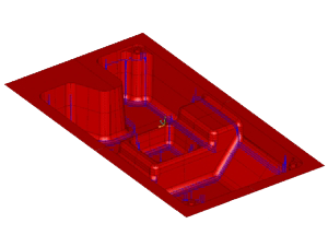
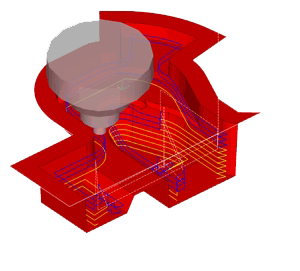
The new algorithms of pocketing and contouring which are useful for high speed machining, always enable tool contact with the work piece, producing elliptic movements to avoid full material tool working. This kind of strategy includes the possibility of defining removal in climb mill, down mill or in two-way mill. Should it be necessary to empty narrow hollows, material engagement is performed with a spiral strategy. Movement among the concentric rings of a toolpath is optimized producing tangent movements. The wide range of available strategies in SUM3D, enables machining in 3, 4 and 5 axis both on 2D profiles and on 3D models.
3 axes machining on profiles (indexed with 2 positioning axes)
While SUM3D was created for 3D machining, it can also give users several 2D machining strategies. Such machining can be applied to simple 2D profiles from 2D IGES or DXF files.
- Flattening.
- Pocketing, with or without islands.
- Contouring, with tool radius compensation managed by a PC or from the CNC with G41/G42 controls.
- Helical contouring of 3D profiles with constant or variable sidestep.
- Engraving or relief starting from texts in True Type™ font, presented along straight lines, circular arcs and possibly mirrored.
- Drilling (threading, centering, boring, etc.)
- Use of ISO cycles or specific cycles for each individual machine tool.
- Recognition of groups by diameter, colour and/or features.
- Pocketing rest material with indication of previous tools used.
3 axis machining on 3D models
- Pocketing with management of the raw part with rest material to maintain a constant machining allowance, rest material related to a previously used tool and optimization of material removal.
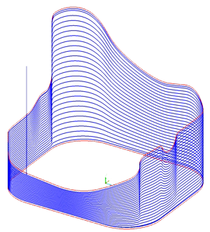
- Z constant or Areas Contouring, with various types of engagement and automatic rest material to maintain the constant scallop.
- Zig/Zag and Unidirectional with strategies for rest material to obtain the constant scallop with the possibility of release management among the passes, with radius, wide tangents, inside surfaces.
- Bitangent
Automatic flat surface machining
- 3D Pocketing with constant increment.
- 2 curves machining: longitudinal, transversal or spiral.
- 3 axis U/V lines machining for fillet or special surface recovery.
- Spiral.
- SpiralCurve machining with three-dimensional model checking.
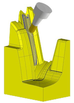
3+2 axis machining on profiles and 3D models
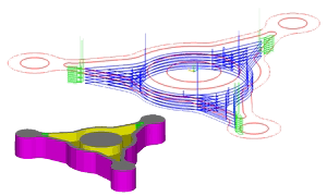
All SUM3D machining can be computed by mandrel axle orientation (positioning of 4th and/or 5th axes) so as to guarantee collision check with tool and its components, creating roto-translation functions of the 4th and 5th axis in the post processed file.
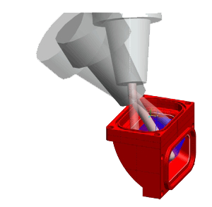
Continuous 5 axis machining on profiles and 3D models
- Curve machining with possibility of continual tool orientation keeping it perpendicular or parallel to the reference surfaces.
- Tool radius compensation management by the SUM3D or CNC through CNC parametric programming.
- 3 axis toolpath conversion created with ball tools, in continuous 5 axis toolpath.
- U/V line machining with the possibility of management of tool advance angle and curves for the identification of the release toolpath in the working area.
- Model machining with selection of a reference surface that defines the continuous inclination of the tool axis.
- Model machining where a profile binds the tool-centre in the 5 axis movements, to permit machining of deep undercut pocket or large punches with spherical tools.
With SUM3D it is possible to set a machining computing precision (roughing, finishing, super-finishing, etc.), leading to the optimization of computing times, related to the machining importance.
The control for computing maximum tool length (set in the tool definition), highlights the areas where computed machining is in collision with the workpiece/mandrel and discards these areas which can be retrieved automatically with a different tool.
If a component is set with the tool, for example the mandrel, machining will be calculated considering such component resulting in increased trajectories to avoid collision.
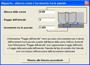
During the phase in which machining parameters are set, it is possible to define the machining step in relation to the desired scallop height by use of a specific window.
Configuration of one or more machinings can be exported creating a file of several machinings that can be used on other models.
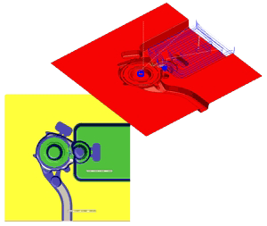
Several systems are available on SUM3D that simulate machining, both for visualization of residual material and for showing the excision of shaving material.
This group of controls permits the graphic visualization of zones of residual material, coloured differently according to the quantity of material remaining.
These areas can be retrieved or used to create a new raw part to work. This function also permits collision checks between the model and toolpath.
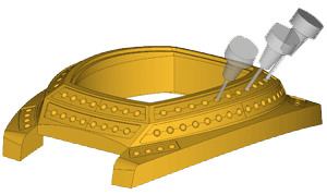
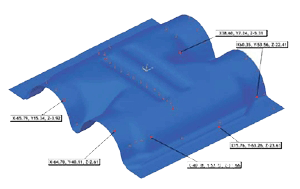
For companies who work in the oil or water market, SUM3D includes procedures that enable radial or spiral toolpath generation to mill valves, pipes and links using machine tools with rotating tables.
As well as all 3, 4 and 5 axes machining available on SUM3D, for the creation of objects in this market sector, there are also special controls which automatically create curves used to mill and drill collets in 5 axes.
Some controls have been included for the footwear market to easily create the models to mill. Different sizes can automatically be produced using the footwear scaling control, starting from a digitized CAD model or a mix of both. The series is performed with scale factors taken from standards, for areas defined by profiles or created by the consumer.
An application that works in Rhinoceros environment (SHOT) is also available which can provide a series of CAD tools for geometry manipulation.
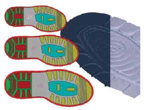
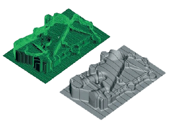
Images from scanner can also be managed by SUM3D, describing their shape, turning them into curves for machining use or for the definition of working surfaces. Starting from a colour or grey-scale bitmap, pictures can be managed through the ZIMAGE option to obtain relief surfaces, by assigning a specific height to each individual colour area.
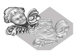
Transforms digitized models into surfaces. It is widely used in the footwear market where, thanks to the use of differentiated scaling functions (heel, toe, sole) different sizes can be created, starting by digitizing the referral model. The same techniques can be applied on helmets, fashion accessories, logo reproduction and parts for the automotive market.
3 AXES TOOLPATH CONVERSION (CNC file) INTO DIFFERENT FILE FORMAT
As well as importing 2D and 3D models, SUM3D permits importation of CNC files in any format (with the exception of fixed cycles). This option gives the user the possibility to convert it to a format that can be read by their own machine tools.
For instance, if post-processed files have already been used with a CNC that is not compatible with the one on the shop-floor, this function enables conversion of the files making them compatible with the machine tools installed.
This SUM3D option permits importation of files that derive from a CNC with a probe or from a dimensional control machine. Such files, complete with the XYZ coordinates of the points measured on the object, will be compared with the SUM3D model. The measured points and gaps can be graphically visualized or supplied on a printed report.
 Overview
 Features
 AMM Module
 Functionalities
 Requirements
 Additional Modules